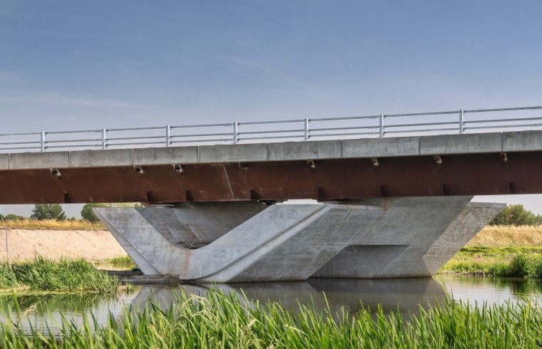
Bridge Formwork
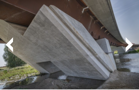
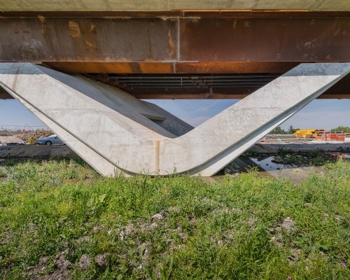
Bridge construction has evolved over the years to combine factors such as function, structural performance and usability, with improved aesthetics. Many modern bridge designs incorporate features that soften the impact of the structure on the environment and provide an element of uniqueness in terms of architecture.
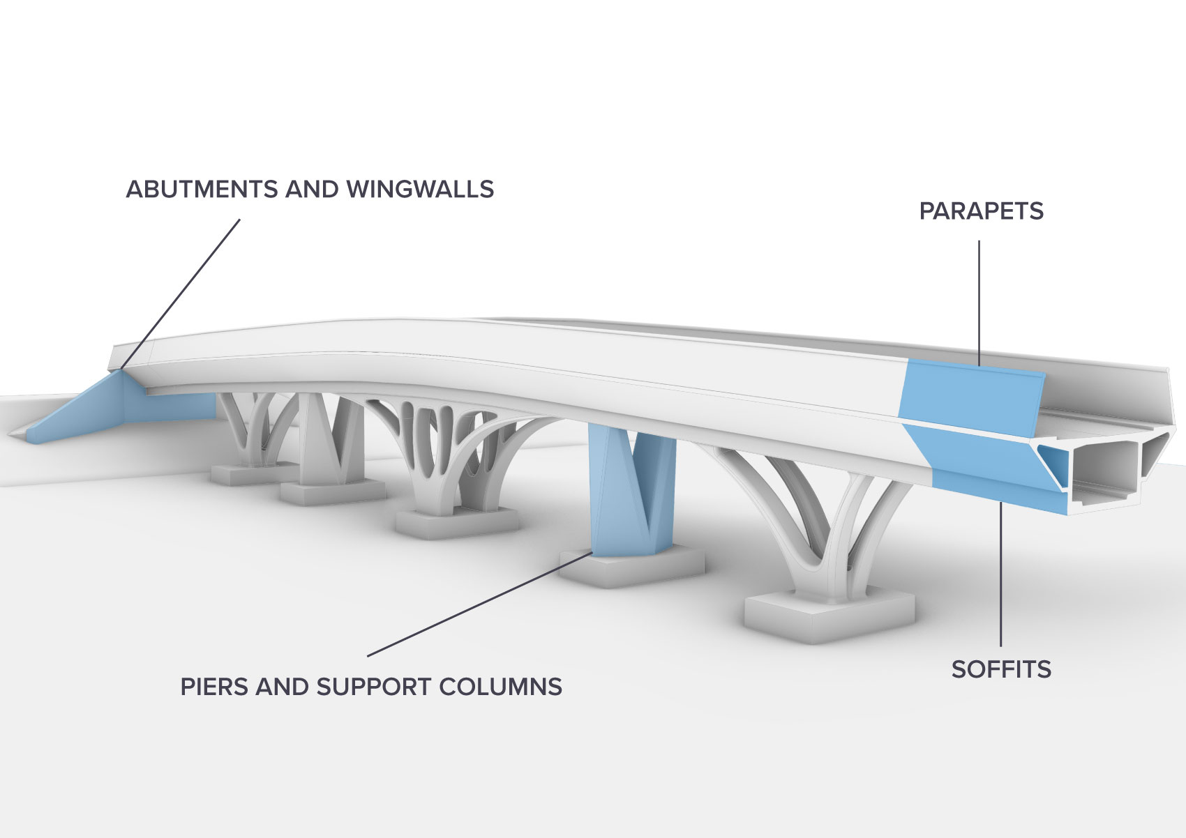
Cordek has previously provided bespoke formwork solutions for bridge related applications including: Abutments & Wingwalls, Parapet Walls, Piers & Support Columns and Soffits.
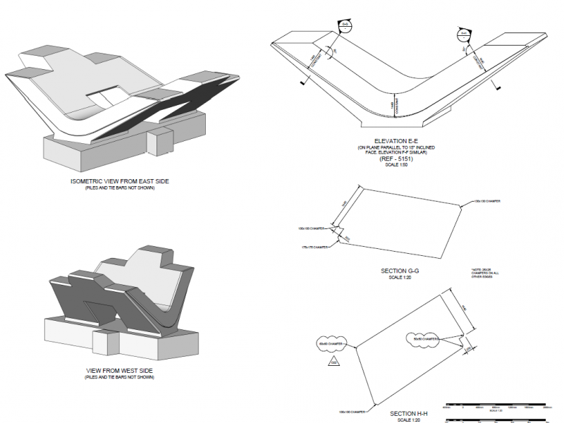
Each bridge former designed by Cordek aims to meet the specific requirements of the project including the size, shape, finish and number of re-uses. Using this information, our designers will select the most appropriate material for each former and create a 3D CAD model for approval, which when accepted will allow CNC machining of the finished formwork solution.
Features
- Manufactured to meet project specific requirements
- Available in a wide range of materials
- CNC machined for consistent, tolerance-controlled surfaces
- Re-usable where applications of the same size, shape and profile are repeated
- Can be supplied in a unitised format for manual handling or limited access purposes
- Basic, Ordinary, Plain & Special Finishes achievable*
*Please refer to National Structural Concrete Specification (NSCS) Edition 4 guidance available below. Formwork solutions can also be provided to meet the requirements of Specification Highways Works: Structural Concrete – Series 1700
Applications
Used for the construction of cast in-situ reinforced concrete bridge structures with either complex or non-standard geometries, profiles and sizes.
Design
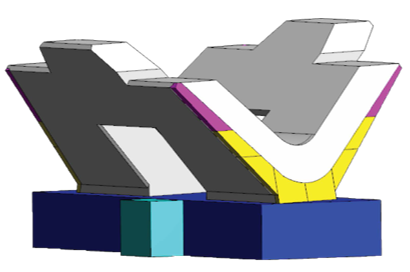
When developing a bridge former design, the following factors should be considered in addition to reviewing any CAD drawings, 3D models, specifications etc that are available:
- Dimensions, geometry and features
- Required concrete finish
- Proposed number of uses – single or multiple
- Loadings – specifically relating to the proposed concrete pour depths
- External structural support method
- Delivery method, unloading requirements and access restrictions
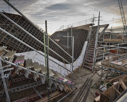
- Positioning, installation and sequence of construction
- Striking, removal and re-use or disposal
Once the project requirements have been confirmed, a conceptual design can be completed along with provision of a quotation confirming proposed material type, features, quantities, manufacturing lead time and costs.
Materials & Finishes
Typically, Cordek bridge formers are manufactured from one of the following material types:
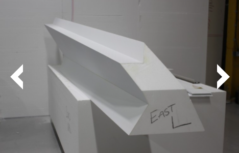
- Filcor Expanded Polystyrene (EPS)
- Filcor EPS with ABS skin
- Filcor EPS with Sheet Fibreglass skin
- Filcor EPS with a spray applied Polyurea skin
- Glass Reinforced Plastic (GRP)
One of the factors determining the most appropriate material used to manufacture a bridge former is the required concrete finish. Further information in relation to the classification of concrete finishes can be found within the National Structural Concrete Specification (NSCS) Edition 4 guidance, a copy of which can be downloaded from the Certification, Guidance and Approval section below.
Manufacture
Once approved, the agreed 3D CAD Model will be converted to CAM data, allowing accurate manufacture of the bridge former via CNC hot wire cutting and / or 5-axis routing dependant on factors such as material type, complexity of shape / profile and required tolerances.
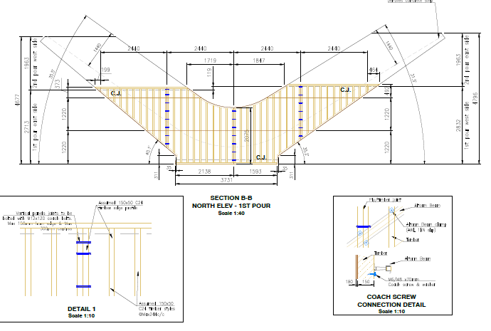
In some instances, due to the required dimensions of the formwork solution, it may comprise of a number of individual units that require assembly on site. This can prove advantageous in certain applications, such as those that have no mechanical handling resource or reduced restricted access.
In cases such as these, features such as tie bolt locations can be incorporated within the design to secure adjoining units together, aiding alignment during the installation process.
User Notice
To view our technical documents, we recommend using alternative internet browsers to Chrome (such as Microsoft Edge, Internet Explorer, or Firefox) whilst Google rectify their Chrome browser and PDF document compatibility issue. We apologise for any inconvenience caused.
